
How to control the electrical resistance of a hot water tank (relay or clock)? Is it necessary to have peak/off-peak operation?
Our SPRING hybrid solar panels are always accompanied by a secondary hot water heating system, which serves as a backup. This can be an electric resistance, a gas boiler, a wood boiler, or an air/water heat pump. Here, we are specifically looking at using an electric resistance as a backup.
It is necessary to check if the water heater's resistance needs to be regulated to prevent it from operating at the same time as our solar panels. The resistance integrated into solar water heaters is typically located above the heat exchanger and operates through a built-in thermostat: it is independent of the control system and does not need to be controlled.
In other cases, a relay or a timer can be installed to regulate the electric resistance.
Use of a relay
The relay is an ON/OFF contactor that will be controlled by the SLL regulation (solar panel regulation) → the regulation will prevent the resistance from operating during programmed hours, and if the set temperature is reached: See here for programming the non-operation hours of the auxiliary heating with the SLL regulation.
A relay is installed surrounded by the following elements:
SLL Regulation → Relay → Circuit breaker → Electric resistance
Note that the circuit breaker can be integrated into some relays. Otherwise, use a 20A circuit breaker for a 3kW resistance.
For finer control of the triggering of the resistance, the "Dualsun SLL" solar regulation allows the electric resistance of the hot water tank to be controlled through three programmable time slots in the regulation.
How to install?
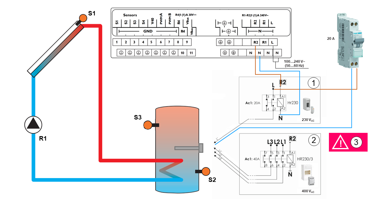
Place a PT1000 temperature sensor in the immersion sleeve at the top of the hot water tank and wire it to terminal S3 of the solar regulation.
Wire a power auxiliary relay as shown in the diagram above:
For a single-phase 230V electric resistance (case 1 in the diagram):
Install a single-phase relay with:
Terminal A1 = Terminal R2 of the SLL regulation
Terminal A2 = Terminal N of the SLL regulation
1 NO (normally open) contact - 20A:
Terminal (1) = Line phase
Terminal (2) = To resistance phase*
1 NC (normally closed) contact - 20A:
Terminal (3) = Do not wire
Terminal (4) = Do not wire
*Wire the neutral of the resistance to the neutral of the power supply.
For a three-phase 400V electric resistance (case 2 in the diagram):
Install a three-phase relay with:
4 NO (normally open) contacts - 40A
Terminal A1 = Terminal R2 of the SLL regulation
Terminal A2 = Terminal N of the SLL regulation
Terminal (1) = Line L1 phase
Terminal (2) = To L1 phase of the resistance*
Terminal (3) = Line L2 phase
Terminal (4) = To L2 phase of the resistance*
Terminal (5) = Line L3 phase
Terminal (6) = To L3 phase of the resistance*
Terminal (7) = Do not wire
Terminal (8) = Do not wire
*Wire the neutral of the resistance to the neutral of the power supply.
How to configure the SLL solar regulation to take into account the presence of a relay?
-Set the system parameter (SYS) = 3
Long press on the validation button

Turn the rotary actuator
until SYS
Activate the modification of the parameter by pressing the validation button for the first time

Turn the rotary actuator
to select system number 3
Validate the selection with the validation button

Press Escape to return to the menu.
-Set the auxiliary heating menu (CA)
Use relay R2 with thermostat function, referencing sensor S3 and with programmable time slots to define.
Long press on the validation button

Turn the rotary actuator
until CA
Activate the modification of parameters by pressing the validation button for the first time

Turn the rotary actuator to adjust the parameters

Validate the selection with the validation button

Settings:
CA0 = 45
CAF = 60
*If a higher hot water comfort is desired, increase the activation setpoint temperature.
Examples of programming time slots according to hot water consumption profile, evening or morning showers:
Evening:
t1O = 16.00
t1F = 23.00
Morning:
t1O = 03.00
t1F = 07.00
Press Escape to return to the menu.

In our systems, the presence of an S3 sensor is mandatory to install a relay. Indeed, the regulation will check two things before activating the backup:
Heating of the tank by the hybrid panels not possible.
Heating of the tank necessary.
For this second constraint, the regulation needs to have visibility on the temperature at the top of the tank, hence the installation of S3.
Peak/off-peak hours
In case the electric resistance does not need to be controlled, it is not essential to install a peak/off-peak operation device. However, this can allow you to pay less for your electricity (by using the resistance only during off-peak hours - for example, at night).
Moreover, using the electric resistance only at night has the advantage of prioritizing heating of the tank by solar panels during the day, which allows for better utilization of solar panels.
IMPORTANT NOTE:
We remind you of the specific requirements that need to be followed for solar water tanks in Dualsun installations:
Use of a timer
A timer is a relay with integrated regulation. In other words, the time slots can be directly programmed on the device, similar to what the SLL regulation did with a relay.
The connections will be as follows:
Electrical panel → Timer → Electric resistance
There is no interaction between a timer and the solar regulation. The timer will control the electric resistance independently of this regulation.
For more information, refer to the timer's manual.