
How to check and change the circulator and the controller on a solar station SLL?
1. Diagnosis of circulator operation
a) Checking the power supply
The green LED on the side of the circulator indicates the presence of 230V voltage when it is flashing.
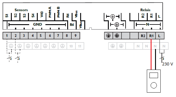
If the LED is off, check the voltage at the output terminals of relay R1 of the controller when it is powered (see figure below).
If V = 230V => check the connection of the power cable to the pump, if it is correct then the pump must be replaced.
If V = 0 V => Replacement of the regulation is necessary.
b) Checking the PWM signal
The regulation generates a DC voltage of about 10 V when the PWM signal controls the pump.
To verify that the PWM output is functional, the voltage at the PWM terminals of the regulation must be measured when the relay has been set to MAN1 = Max* and one of the 2 cables has been removed from the regulation (see figure below).
If V = 10 V => replacement of the pump is necessary.
If V = 0 V => replacement of the regulation required.
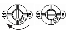
* NB : To switch to forced operation, use the

button then validate MAN1, change the value with the knob to the desired value and then validate again with the button

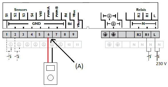
(A) = Disconnect this this strand before measurement
2- Regulation replacement
Before any operation of unwiring of the regulation in place, remember to take one or more photos of the existing wiring to be able to redo it identically.
Before switching the power supply of the existing regulation off, remember to note the following information in order to re-parameterise it identically in the new regulation:
System number
Tank heater (number and mode)
Relay control type (number and mode)
Minimum and maximum relay speed (number and value)
Auxiliary heating (CA O; CA F; t1 O; t1 F; t2 O; t2 F)
Manual mode (number and mode)
Parallel relay option (REL; REL R; inverted mode ON or OFF)
Calorimeter option (if ON: VART; DMAX; GELT; GELT%; SDCAL; SRCAL)
To help you navigate through the menu please use the control manual supplied with the solar station. (Also available on request at pro@dualsun.fr).
Once these 2 steps have been completed, it is possible to unwire everything and then remove the controller from the solar station. To do this please follow the steps below:
Remove the front cover of the controller held by a cruciform screw.
Unclip the upper part by pulling on the upper corners.
Unscrew the retaining screw at the bottom
Slightly pull the electronic board out of its slot to unscrew the high retaining screw.
Take it off
Proceed in reverse order to install the new control.
3- Replacement of the circulator
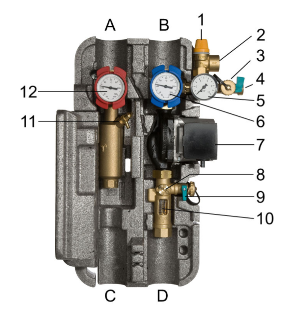
The circulator is marked (7) in figure below:
Switch off the pump by unplugging the regulator.
Disconnect the 2 pump cables (power and PWM).
Close the blue ball valve (6) - horizontal
Turn the flow meter valve (8) 90° clockwise - horizontal (see figure below).
Open the drain valve (9).
The heat transfer medium in the pump can now flow out.
Unscrew the union nut on the top side of the pump to drain the pump.
After this, dismantle the pump and assemble the replacement pump.
Reconnect the 2 pump cables.
Open the blue ball valve (6) - vertical.
Return the flow meter valve (8) to its initial position - vertical, flat at the bottom.
Turn on the pump to start it, do not hesitate to make successive start/stop to prime it if it cavitates at start-up.
Run the pump in forced operation: MAN1 = Max
Adjust the operating flow rate by turning the flow meter valve (8):
Operating flow rate = 1 L/min/panel x Number_SPRING_panels
Switch the pump to automatic mode: MAN1 = Auto
To go further : Which solar controllers are compatible with Dualsun?