
How are the by-pass diodes positioned in the Dualsun Shingle panels?
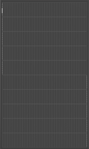
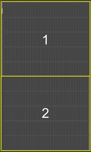
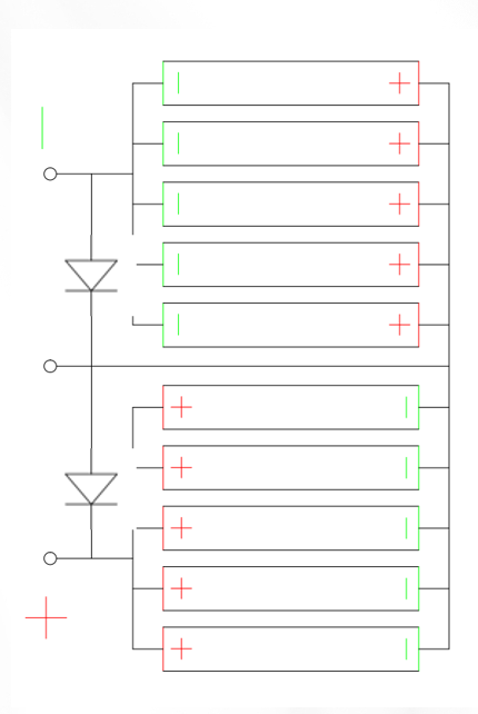
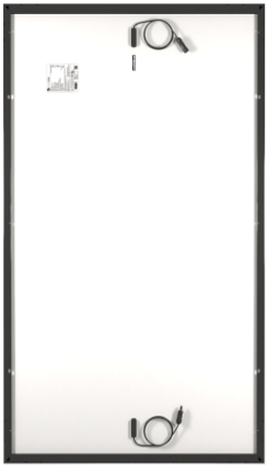
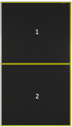
The cells of the Dualsun Shingle 375, 400 and 425 panels are arranged in 10 parallel columns and in 2 groups. The two groups of cells are protected by two 15A bypass diodes. The junction box is installed between the two groups of cells.
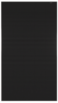
FLASH 375 Shingle Black :
|
|
|
|
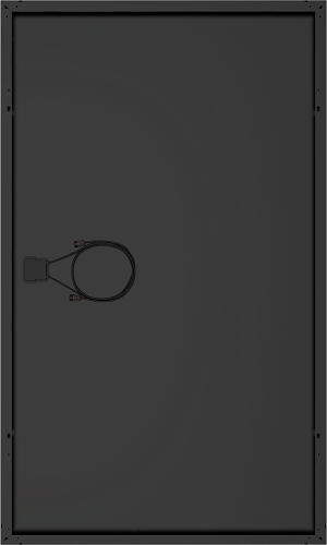
FLASH 425 Shingle Black:
|
|
|
|
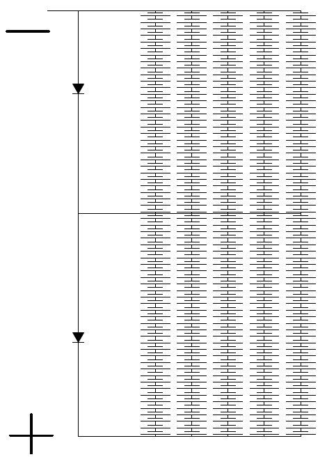
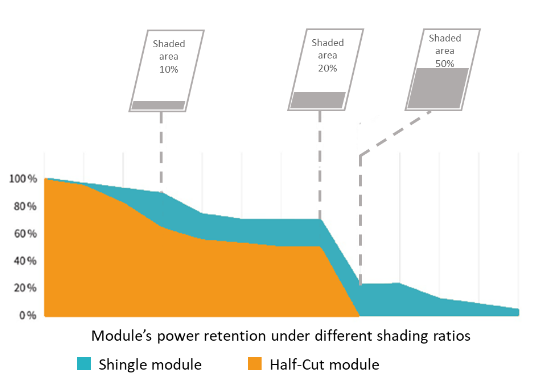
The layout in 10 parallel columns significantly reduces the shading effect on the cells.
Indeed, in a branch circuit the intensity in the main branch is equal to the sum of the intensities of all the derived branches (law of additivity). Concretely, if one of the 10 columns is impacted by shading, a leaf or bird droppings, the intensity produced by the module will be equal to the sum of the intensities of each column. In other words, only the shaded column will see its production reduced, not impacting the production of the other 9 columns.
Note: For comparison, on a Full Cell or Half-Cut technology module, the module is respectively composed of 3 and 6 separate columns in parallel. The impact of shading is therefore greater on these technologies.
To go further : What are the photovoltaic specifications of Dualsun panel?